Category: LAN/WAN

Cisco SD-WAN ISR 4k Getting Started – Part 2 – Bootstrap Process

Reading Time: 5 minutes

The Bootstrap Process

In the Part 1 of this series we covered the first step to converting and ISR from IOS-XE onto the Cisco SD-WAN platform. We will continue from there with my story of frustrations and the discovered caveats and need to knows. Starting first with bootstrapping the ISR.

Continue reading
Share this article:

Permanent link to this article: https://www.packetpilot.com/cisco-sd-wan-isr-4k-getting-started-part-2-bootstrap-process/

Cisco SD-WAN ISR 4k Getting Started – Part 1 – Upgrading Code

Reading Time: 3 minutes

Upgrading from IOS-XE to SD-WAN Code

Recently I was building out a lab to iron out a migration onto the Cisco SD-WAN (Viptela) solution. As part of that process existing ISR 4k routers were going to be used at the edge devices. This process, while fairly straight forward, came with a few “gotchas” and “snags” that I had to work through. In this post I will cover the upgrade of the ISR onto SD-WAN code. In the next post I will cover the bootstrap process as well as a couple of caveats related to vManage and the ISR4k routers.

Continue reading
Share this article:

Permanent link to this article: https://www.packetpilot.com/cisco-sd-wan-isr-4k-getting-started-part-1-upgrading-code/

Bulk enable PIM via TCL

Reading Time: 3 minutesI’ve been working on doing some multicast labs lately and am constantly resetting my lab devices to their default configs and starting from scratch. As many of us know, to enable PIM on all of your interfaces you must go into each interface and enable it manually. There is no default command to enable PIM on all interfaces. We know PIM should be enabled 1 to 1 with interfaces involved in routing making this a boon. With that in mind, and the fact that I am rather comfortable with the concept of needing PIM on the interfaces, and likely speak and type this command in my sleep, I decided to make it easier and modify a previous TCL script I had written to enable PIM on every interface that has an IP address assigned to it. With the great “Send to Chat” feature of SecureCRT I can do this across my entire topology on one fell swoop. In a real world environment, you could use a tool like Solarwinds to push this out to your devices.

Continue reading

Share this article:

Permanent link to this article: https://www.packetpilot.com/bulk-enable-pim-via-tcl/

Route-Targets Explained

Reading Time: 3 minutes 

As I began to study MPLS L3VPNs I was excited to start flinging my fingers around the keyboard. However, I ran into a little snafu during my learning. All of the videos and configuration example I was finding didn’t separate the difference between the Route Distinguisher (RD) and the Route Targets. Most of the examples simply matched the RD to the Route Targets and/or used the same Route Targets for both import and export. This left me feeling like I wasn’t really understanding what those commands and numbers were accomplishing. I decided to make a visual representation to make it easier to understand.

Router-Target Policy Visualization

Router-Target Policy Visualization

To make this concept easier to understand we first need to know that the RD does not dictate what routes a route will import or export into it’s PE-CE routing process. The purpose of the RD so to add an additional label to prefixes so overlaps can be inserted in the BGP table and shared amongst the various PE routers. For example, my RD of 65000:8 indicates any routers in the BGP table from my customer vrf would indicate a prefix of 10.20.30.40 as 65000:8:10.20.30.40. This means if another vrf with a different RD of 4242:42 could also install 10.20.30.40 in the providers BGP table as 4242:42:10.20.30.40.

Now that we are clear on the use of the RD we can move onto the Route Targets. There are two route targets we define in our VRF policy. The import and export targets. Many examples and videos show these as the same (which is a perfectly valid configuration) often times matching the RD. To clarify exactly what they are used for I have used three different Router Targets. I am going to correlate their indicators with colors to make the example easier to visualize.

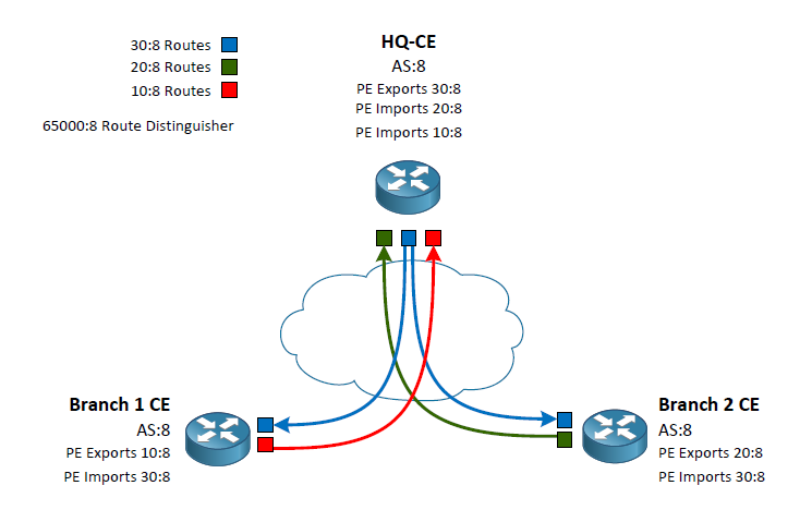
Routes exported from the headquarters use 30:8 which we will call the “Blue Routes”
Routes exported from Branch 1 will use 10:8 which we will call the “Red Router”
Routes exported from Branch 2 will use 20:8 which we will call the “Green Routes”

This exporting is done by the PE routers connecting to the CE routers. The CE routers in this example our peering via eBGP with the PE routers inside of a VRF. The VRF configuration on the PE routers is what indicates the Router Target identifier to export. At this point we can write a policy of which routers should be allowed into the individual CE routes using the VRF Route Target import. Lets follow a case from the HQ to Branch 1.

HQ CE peers with its PE router which has a VRF policy stating to export its routes as the color Blue. These routes are passed around to the other PE routers. When the Branch 1 PE peer receives the routes it sees that it’s VRF policy is stating to export its routes as the color Red as well as import any routes that are colored Blue. Back at the headquarters we have our VRF policy set to import both the Red and Green routes. Branch 2 does the same as Branch 1 but swapping out Red for Green.

By writing the VRF policies this way we have created a Branch to HQ connection while not passing routes Branch to Branch. In my diagram I show the routes coming into the CE routes as it is the ultimate end goal however, please keep in mind that the VRF configuration is done on the PE routes.

I hope that by using simple colors for the routes it has simplified the reasons we use the RD, and the import and export Route Target. I found it difficult to understand the true use of these configuration when they were using the same value for the RD as well as the import and export Route Targets.


Share this article:

Permanent link to this article: https://www.packetpilot.com/route-targets-explained/

Synapps Paging Delays – An HTTP/TCP Wireshark diagnosis

Reading Time: 5 minutesThe Scenario goes like this: A Synapps – SA Announce paging and messaging server integrated with Cisco’s CUCM hosting around 30 phone to phone paging groups. The paging had been working fine for months and out of no where one of thirty particular groups was putting in multiple trouble tickets over multiple days that the paging isn’t working.

So begins the troubleshooting and diagnosis. My first action was to monitor the paging server as it has a real time display of who is calling a paging group and which group they are calling at in given time. When I was monitoring this I could see multiple people calling multiple groups including the one in question. So this brings up one of those “what gives” questions. Are they just doing something wrong up in the area. Time to take a trip and raise that pedometer count.

I arrive in the area and try and locate and area where I can visually see and hear multiple phones. Easier said than done but in this case I was the only one available to work on the issue and knowing that the paging server will activate the speakerphone and mute lights when a group the phone is a member of is called this was my best bet and understanding what was going on. After making my first test page I can see that lights on the phones I can see are immediately lighting up, however I can’t hear audio. As I stand there dumbfounded with the phone still off hook all of a sudden the audio starts picking up the background noise. However, paging shouldn’t have a 6 second delay before you can start talking. Six seconds is a long time to wait after hitting page to start talking. So whats going on? It’s only one group experiencing this. What is different about their group? Time for a deep dive in the diagnostics world. Enter Wireshark.

Continue reading

Share this article:

Permanent link to this article: https://www.packetpilot.com/it-was-broke-but-the-sharks-got-to-it/

Trouble shoot with TDR

Reading Time: 5 minutesThis article is another example of trouble shooting by putting multiple pieces together. While it relies upon existing knowledge of the environment in which the article is based it should prove to be a good example of a trouble shooting process that will hopefully be able to spark some creative thinking the next time you have a problem that needs to be resolved.

The scenario starts out with a user ticket stating that the phone isn’t working. After some fact gathering the below details and possible solutions were outlined.
Continue reading

Share this article:

Permanent link to this article: https://www.packetpilot.com/trouble-shoot-with-tdr/

SRT: Offline type 7 decrypt

Reading Time: < 1 minutesI was recently working on deploying a new device into our network infrastructure. I was working off a configuration template that had a standard arguments for AAA leveraging TACACS+. I was offsite and had asked a fellow colleague to enter the new device into our ACS deployment to allow authentication and command authorization. The long and short of it is, it was copied off of a different group of devices than what my configuration template was based of. The issue was a mismatch in TACACS server keys. The problem was I was currently offline as I was connecting to the device what would let me out to the network. So what is the stupid router trick? The stupid router trick consists of using the key chains to decrypt a type 7 TACACS (or other key) that is hidden via service password-encryption in your configuration template. The trick is pretty simple. Create a temporary key chain that won’t be applied anywhere, enter the key(s) into the key chain in their type 7 format, and then do a simple show key chains. Really! That’s all there is to it. See the output below.


R1(config)#key chain tempkeys
R1(config-keychain)#key 1
R1(config-keychain-key)#key-string 7 06150A225E4B1D12000E
R1(config-keychain-key)#exit
R1(config-keychain)#key 2
R1(config-keychain-key)#key-st
R1(config-keychain-key)#key-string 7 095F4B0A0B0003190E15
R1(config-keychain-key)#end
R1#
R1#show key chain
Key-chain tempkeys:
key 1 -- text "secretkey"
accept lifetime (always valid) - (always valid) [valid now]
send lifetime (always valid) - (always valid) [valid now]
key 2 -- text "secretkey"
accept lifetime (always valid) - (always valid) [valid now]
send lifetime (always valid) - (always valid) [valid now]
Share this article:

Permanent link to this article: https://www.packetpilot.com/srt-offline-type-7-decrypt/

Tracked Static Default Route

Reading Time: 6 minutesAs common place in today’s networks redundancy is key. Applications are the key components to business obtaining revenue. More and more applications are becoming SaaS and ecommerce is here to stay. With that being said, many companies are moving to redundant connections to the internet. These connections could be through two different ISPs, or both connections to the same ISP. Often times these connections will be of different speeds to save on costs. The key to these connections is to maintain internet connectivity.

Continue reading

Share this article:

Permanent link to this article: https://www.packetpilot.com/tracked-static-default-route/

Cisco OSPF MD5 Authentication

Reading Time: 2 minutesContinuing with our OSPF and interior gateway protocols we will not look at an MD5 implementation utilizing OSPF on a Cisco router. We will again continue with our 3 router topology as used in both the EIGRP MD5 example and the OSPF plain text example. There are very few changes that will need to be made to our earlier OSPF example using plain text. The topology is as follows.

Continue reading

Share this article:

Permanent link to this article: https://www.packetpilot.com/cisco-ospf-md5-authentication/

Cisco OSPF Plain Text Authentication

Reading Time: 2 minutesContinuing with our interior routing protocol discussion on authentication we are going to look at Cisco OSPF implementation of plain text authentication. While this isn’t the most widely used model for authentation with OSPF it is a viable option. The topology we are going to use is the same topology from the EIGRP authentication example. The steps may feel familiar as well.

Continue reading

Share this article:

Permanent link to this article: https://www.packetpilot.com/cisco-ospf-plain-text-authentication/

Load more