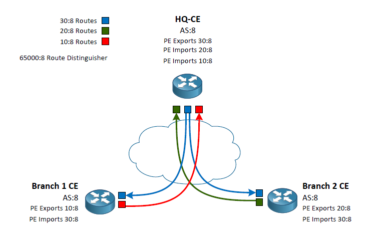
As I began to study MPLS L3VPNs I was excited to start flinging my fingers around the keyboard. However, I ran into a little snafu during my learning. All of the videos and configuration example I was finding didn’t separate the difference between the Route Distinguisher (RD) and the Route Targets. Most of the examples simply matched the RD to the Route Targets and/or used the same Route Targets for both import and export. This left me feeling like I wasn’t really understanding what those commands and numbers were accomplishing. I decided to make a visual representation to make it easier to understand.
To make this concept easier to understand we first need to know that the RD does not dictate what routes a route will import or export into it’s PE-CE routing process. The purpose of the RD so to add an additional label to prefixes so overlaps can be inserted in the BGP table and shared amongst the various PE routers. For example, my RD of 65000:8 indicates any routers in the BGP table from my customer vrf would indicate a prefix of 10.20.30.40 as 65000:8:10.20.30.40. This means if another vrf with a different RD of 4242:42 could also install 10.20.30.40 in the providers BGP table as 4242:42:10.20.30.40.
Now that we are clear on the use of the RD we can move onto the Route Targets. There are two route targets we define in our VRF policy. The import and export targets. Many examples and videos show these as the same (which is a perfectly valid configuration) often times matching the RD. To clarify exactly what they are used for I have used three different Router Targets. I am going to correlate their indicators with colors to make the example easier to visualize.
Routes exported from the headquarters use 30:8 which we will call the “Blue Routes”
Routes exported from Branch 1 will use 10:8 which we will call the “Red Router”
Routes exported from Branch 2 will use 20:8 which we will call the “Green Routes”
This exporting is done by the PE routers connecting to the CE routers. The CE routers in this example our peering via eBGP with the PE routers inside of a VRF. The VRF configuration on the PE routers is what indicates the Router Target identifier to export. At this point we can write a policy of which routers should be allowed into the individual CE routes using the VRF Route Target import. Lets follow a case from the HQ to Branch 1.
HQ CE peers with its PE router which has a VRF policy stating to export its routes as the color Blue. These routes are passed around to the other PE routers. When the Branch 1 PE peer receives the routes it sees that it’s VRF policy is stating to export its routes as the color Red as well as import any routes that are colored Blue. Back at the headquarters we have our VRF policy set to import both the Red and Green routes. Branch 2 does the same as Branch 1 but swapping out Red for Green.
By writing the VRF policies this way we have created a Branch to HQ connection while not passing routes Branch to Branch. In my diagram I show the routes coming into the CE routes as it is the ultimate end goal however, please keep in mind that the VRF configuration is done on the PE routes.
I hope that by using simple colors for the routes it has simplified the reasons we use the RD, and the import and export Route Target. I found it difficult to understand the true use of these configuration when they were using the same value for the RD as well as the import and export Route Targets.

