Last year I was involved in assisting a datacenter core and access-layer refresh. In this case the IDF’s were reusing existing fiber patches and the run to the datacenter stayed in place. however, within the datacenter core equipment was placed across the room required new cross connects to be ran to the new core cabinet. When the cutovers began to take place the IDF’s were spread out over a large campus. Meaning troubleshooting by walking back and forth to check cabling was extremely time consuming and inefficient. Since all the IDF’s were connected via port channels I was able to figure out which runs were crossed and go fix them all at once using only the ether channel show output. I’ll walk you through the process now.
In this demonstration I am using two 3850 switches as output and the command being used is “show etherchannel detail”
We are first going to look at the IDF’s view and map out the connectivity. Note that the information we are focused on is the Local port number and the partners port number. In this example we are going to use the Hexidecimal Port Number value.
Port state    = Up Mstr Assoc Not-in-Bndl
Channel group = 4           Mode = Active          Gcchange = -
Port-channel  = Po4         GC   =   -             Pseudo port-channel = Po4
Port index    = 0           Load = 0x00            Protocol =   LACP

Flags:  S - Device is sending Slow LACPDUs   F - Device is sending fast LACPDUs.
        A - Device is in active mode.        P - Device is in passive mode.

Local information:
                            LACP port     Admin     Oper    Port        Port
Port      Flags   State     Priority      Key       Key     Number      State
Gi1/0/51  SA      bndl      32768         0x4       0x4     0x134       0xD

Partner's information:

                  LACP port                        Admin  Oper   Port    Port
Port      Flags   Priority  Dev ID          Age    key    Key    Number  State
Gi1/0/51  SA      32768     001f.260d.bd80   0s    0x0    0x2A   0x11C   0x5

Age of the port in the current state: 0d:00h:00m:30s

Port: Gi1/0/52
------------

Port state    = Up Mstr Assoc Not-in-Bndl
Channel group = 4           Mode = Active          Gcchange = -
Port-channel  = Po4         GC   =   -             Pseudo port-channel = Po4
Port index    = 0           Load = 0x00            Protocol =   LACP

Flags:  S - Device is sending Slow LACPDUs   F - Device is sending fast LACPDUs.
        A - Device is in active mode.        P - Device is in passive mode.

Local information:
                            LACP port     Admin     Oper    Port        Port
Port      Flags   State     Priority      Key       Key     Number      State
Gi1/0/52  SA      bndl      32768         0x4       0x4     0x135       0xD

Partner's information:

                  LACP port                        Admin  Oper   Port    Port
Port      Flags   Priority  Dev ID          Age    key    Key    Number  State
Gi1/0/52  SA      32768     001f.260d.bd80   0s    0x0    0x2A   0x11D   0x5

Age of the port in the current state: 0d:00h:00m:32s
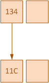
Now we can begin mapping out the connectivity between the two switches. In this case the two switches are connected via a 2 link port channel. Using the output above from the IDF view we will first write down the first port and who it’s partner port is. In this case our local port is 0x134 and we are connected to our partners port 0x11C. Note the arrow drawn to indicated the view direction.
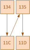
We will not continue the process for the next port indicated by lines 36 and 42 in the above output. Again drawing the line with an arrow to indicate the direction of the view. In this case our port 0x135 is connected to our partners port 0x11D
At this point we log into the other switch and repeat the process of drawing our connectivity from it’s point of view. We again look at the same output on switch 2.
Port state    = Up Mstr Assoc Not-in-Bndl
Channel group = 42          Mode = Active          Gcchange = -
Port-channel  = Po42        GC   =   -             Pseudo port-channel = Po42
Port index    = 0           Load = 0x00            Protocol =   LACP

Flags:  S - Device is sending Slow LACPDUs   F - Device is sending fast LACPDUs.
        A - Device is in active mode.        P - Device is in passive mode.

Local information:
                            LACP port     Admin     Oper    Port        Port
Port      Flags   State     Priority      Key       Key     Number      State
Gi1/0/3   SA      bndl      32768         0x2A      0x2A    0x11C       0xD

Partner's information:

                  LACP port                        Admin  Oper   Port    Port
Port      Flags   Priority  Dev ID          Age    key    Key    Number  State
Gi1/0/3   SA      32768     64d8.149a.1a00   0s    0x0    0x4    0x135   0x5

Age of the port in the current state: 0d:00h:01m:33s

Port: Gi1/0/4
------------

Port state    = Up Mstr Assoc Not-in-Bndl
Channel group = 42          Mode = Active          Gcchange = -
Port-channel  = Po42        GC   =   -             Pseudo port-channel = Po42
Port index    = 0           Load = 0x00            Protocol =   LACP

Flags:  S - Device is sending Slow LACPDUs   F - Device is sending fast LACPDUs.
        A - Device is in active mode.        P - Device is in passive mode.

Local information:
                            LACP port     Admin     Oper    Port        Port
Port      Flags   State     Priority      Key       Key     Number      State
Gi1/0/4   SA      bndl      32768         0x2A      0x2A    0x11D       0xD

Partner's information:

                  LACP port                        Admin  Oper   Port    Port
Port      Flags   Priority  Dev ID          Age    key    Key    Number  State
Gi1/0/4   SA      32768     64d8.149a.1a00   0s    0x0    0x4    0x134   0x5

Age of the port in the current state: 0d:00h:01m:33s
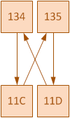
With this output we will look at ports ones information on lines 12 and 18 and draw our connectivity between the local port and the partners port. Again, use an arrow to indicate view direction. In this case we see that local port 0x11C is connected to partner port 0x135.
Looking at the next ports information on lines 36 and 42 we can see that our local port 0x11D is connected to partner port 0x134. Draw this in with an arrow indicated direction of view.
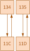
We can now see that somewhere within the fiber runs the send and receives have been crossed. Other results could show the send is connected to an entirely wrong port or even more crossing of wires. A correct view would have the local ports and partner ports mutually agree from both switches views as indicated below.
As you can see this can help you learn of incorrectly terminated fiber with this information. Knowing that the original IDF patches and the original run to the data center are still in place being used we know to look specifically at the new cross connect and which specific pairs of fibers.


