
Say you have a network that currently has an MPLS WAN from your HQ to all of your Branches. You want to migrate these MPLS connections into a DMVPN design and in doing that, you would like to move the MPLS links into a Front Door VRF. There comes a challenge with this move in regards to the routing tables and when to move the headend.
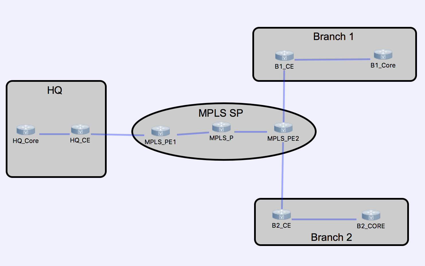
The topology used in the following demonstration is below:
A common approach would be to migrate all of the spokes into their new VRF and then flash cut the headend into it’s VRF. However, there is an inherent risk in this approach. While you can pre-stage the DMVPN tunnels on all of the spokes the migration process would look similar to this:
Migrate MPLS connection on spoke to FVRF
Migrate MPLS BGP peering on spoke to VRF Aware
Leak VRF RIB into Global RIB on spoke
Pre-stage FVRF aware DMVPN Tunnel
Pre-stage Overlay routing protocol
Repeat for each spoke.
At this point our Spokes should be pre-staged and we will migrate the headend. Here is where the challenge comes in. If there is an issue on the headend, or the spoke configurations, we could be in a situation where all spokes are down for an extended period of time while we figure out where the issue in routing lies. In my opinion a better approach is to pre-stage and cutover the headend first. With proper planning we can migrate spokes individually, one at a time while maintaining full connectivity.
Here is our challenge scenario:
At our headend our datacenter core has an OSPF peering to our MPLS CE router. Our MPLS provider peers PE-CE with eBGP. Mutual OSPF to BGP redistribution is occurring on the CE router. We want make this CE router our DMVPN headend with EIGRP as the overlay protocol allowing summarization to the spokes for a Phase 3 DMVPN. I’ve worked out the following strategy in such a way to allow our Headend router to be cutover in a “pre-staged” DMVPN which will allow full connectivity between migrated and un migrated spokes utilizing our new Overlay routing protocol. In this strategy we maintain the headend PC-CE eBGP peering until the very end.
Since our spokes will be using either the BGP underlay peering or EIGRP overlay peering at a given time as the primary means of learning prefixes destinations redistribution will be required at the headend between BGP & OSPF, as well as EIGRP & OSPF. The following outlines the redistribution requirements.
All BGP routes will be redistributed into OSPF. This is already occurring due to the MPLS eBGP peering with the SP and OSPF being the primary infrastructure routing protocol at the headend.
EIGRP will also be redistributed into OSPF as once a spoke has been migrated to DMVPN the headend will be learning the respective spokes routes via EIGRP.
OSPF is redistributed into BGP to facilitate the headend subnets reaching non-migrated sites.
EIGRP will need to be redistributed into BGP to facilitate non-migrated sites learning prefixes of migrated sites. Since EIGRP has a more preferred AD then OSPF the headend will see migrated spokes as EIGRP routes not OSPF routes. Care will be taken to now leak the summary address(es) or the overlay tunnel address into BGP causing tunnel issues.
First we will look at the headend routing table before we stage and perform the cutover:
Gateway of last resort is not set

      10.0.0.0/8 is variably subnetted, 9 subnets, 3 masks
O        10.10.10.0/24 [110/2] via 10.16.16.2, 00:37:09, GigabitEthernet0/2
C        10.16.16.0/30 is directly connected, GigabitEthernet0/2
L        10.16.16.1/32 is directly connected, GigabitEthernet0/2
O        10.20.20.0/24 [110/2] via 10.16.16.2, 00:37:09, GigabitEthernet0/2
B        10.57.57.0/30 [20/0] via 172.16.42.1, 00:36:01
B        10.89.89.0/30 [20/0] via 172.16.42.1, 00:09:16
B        10.130.130.0/24 [20/0] via 172.16.42.1, 00:14:46
B        10.140.140.0/24 [20/0] via 172.16.42.1, 00:06:44
B        10.250.250.0/24 [20/0] via 172.16.42.1, 00:08:45
      172.16.0.0/16 is variably subnetted, 2 subnets, 2 masks
C        172.16.42.0/30 is directly connected, GigabitEthernet0/1
L        172.16.42.2/32 is directly connected, GigabitEthernet0/1
      172.20.0.0/30 is subnetted, 1 subnets
B        172.20.42.0 [20/0] via 172.16.42.1, 00:19:34
      172.31.0.0/30 is subnetted, 1 subnets
B        172.31.42.0 [20/0] via 172.16.42.1, 00:36:01
The first part of the strategy is going to be planning the route-map and prefix lists needed for the FVRF to Global and Global to FVRF route table leaking on the headend CE. In this case I am going to simply allow all prefixes to be leaked between to two creating a simple prefix-list and route-map configuration:
ip prefix-list FVRF_LEAK seq 5 permit 0.0.0.0/0 le 32
!
route-map FVRF_LEAK permit 10
 match ip address prefix-list FVRF_LEAK
Next we will pre-stage the VRF Configuration to allow the leaks between the two routing tables as well as prestige the default route required for the FVRF. In this case, the default route will point to what is currently the eBGP neighbor. In lobbing both the rd as well as the route-targets were required for this to function properly:
vrf definition FVRF_MPLS
 rd 100:100
 route-target export 100:100
 route-target import 100:100
 !
 address-family ipv4
  import ipv4 unicast 500 map FVRF_LEAK
  export ipv4 unicast 500 map FVRF_LEAK
 exit-address-family
!
!
Ip route vrf FVRF_MPLS 0.0.0.0 0.0.0.0 172.16.42.1
!
Before we migrate the PE facing interface into the VRF as well as prior to migrating the eBGP peering to VRF aware lets look at the current eBGP configuration.
router bgp 65100
 bgp log-neighbor-changes
 redistribute ospf 42 metric 100 match internal external 1 external 2
 neighbor 172.16.42.1 remote-as 234
At this point we will add the VRF aware configuration for eBGP. This requires adding the existing neighbor underneath the address-family ipv4 vrf command. Below is the finished output of our BGP configuration at this point:
router bgp 65100
 bgp log-neighbor-changes
 redistribute ospf 42 metric 100 match internal external 1 external 2
 neighbor 172.16.42.1 remote-as 234
 !
 address-family ipv4 vrf FVRF_MPLS
  neighbor 172.16.42.1 remote-as 234
  neighbor 172.16.42.1 activate
 exit-address-family
Now I am going to pre-stage the CE Tunnel interface. For simplicity in this post I am going to leave of crypto. Below is the basic DMVPN headend tunnel configuration. Notice the tunnel VRF command. This allows this tunnel interface to be pre-staged for the first spoke migration. Also take special note that at this time redirects are turned off. They will be turned on after the final spoke has been migrated:
interface Tunnel10
 ip address 192.168.242.1 255.255.255.0
 no ip redirects
 ip nhrp authentication MPLSFVRF
 ip nhrp map multicast dynamic
 ip nhrp network-id 10
 tunnel source GigabitEthernet0/1
 tunnel mode gre multipoint
 tunnel vrf FVRF_MPLS
end
The next step is to pre-stage the overlay routing protocol on the CE. In this case we are going to use EIGRP and summarize the address space down the tunnel. For simplicity I have left off items such as authentication that would traditionally be used in a production deployment:
router eigrp FVRFMPLS
 !
 address-family ipv4 unicast autonomous-system 200
  !
  af-interface default
   passive-interface
  exit-af-interface
  !
  af-interface Tunnel10
   summary-address 10.0.0.0 255.0.0.0
   no passive-interface
   no split-horizon
  exit-af-interface
  !
  topology base
  exit-af-topology
  network 192.168.242.0
 exit-address-family
Now we need to create our protection route-map for redistributing EIGRP into BGP. Afterwords we will redistribute EIGRP into both BGP and OSPF. The following prefix list denies the overlay tunnel prefix as well as the summary prefix.
ip prefix-list EIGRP_BGP_OVERLAY_BLOCK seq 5 permit 192.168.242.0/24
Ip prefix-list EIGRP_BGP_OVERLAY_BLOCK permit 10.0.0.0/8

Route-map EIGRP_BGP deny 10
Match IP address prefix-list EIGRP_BGP_OVERLAY_BLOCK
route-map EIGRP-BGP permit 20
Now we will redistribute EIGRP into both OSPF and BGP on the CE router. The final output is shown below:
router bgp 65100
 bgp log-neighbor-changes
 redistribute ospf 42 metric 100 match internal external 1 external 2
 redistribute eigrp 200 route-map EIGRP_BGP
 neighbor 172.16.42.1 remote-as 234
 !
 address-family ipv4 vrf FVRF_MPLS
  neighbor 172.16.42.1 remote-as 234
  neighbor 172.16.42.1 activate
 exit-address-family
!
!
router ospf 42
 redistribute bgp 65100 subnets
 redistribute eigrp 200 subnets
We are now ready to migrate the CE MPLS interface into the FVRF. This will naturally cause a short outage while the new VRF aware BGP peering comes up and routes are leaked into the global routing table. After this is done however, the CE router will be able to route traffic for both migrated and non-migrated spokes. That is, MPLS native spokes and DMVPN over FVRF MPLS Spokes:
As you can see and are likely aware, once you add the interface to the VRF the IP address is removed, the tunnel interface will go down and then up, and the original BGP peering goes down. After a short time the new VRF aware BGP peering comes up.
Router(config)#int gi0/1
Router(config-if)#vrf forwarding FVRF_MPLS
% Interface GigabitEthernet0/1 IPv4 disabled and address(es) removed due to enabling VRF FVRF_MPLS
*May 17 20:16:52.157: %LINEPROTO-5-UPDOWN: Line protocol on Interface Tunnel10, changed state to down
Router#
Router#
Router(config-if)#ip address 172.16.42.2 255.255.255.252
Router(config-if)#end
Router#
Router#
*May 17 20:16:57.727: %LINEPROTO-5-UPDOWN: Line protocol on Interface Tunnel10, changed state to up
*May 17 20:16:58.592: %SYS-5-CONFIG_I: Configured from console by console
Router#
Router#
*May 17 20:17:00.948: %BGP-3-NOTIFICATION: received from neighbor 172.16.42.1 active 6/7 (Connection Collision Resolution) 0 bytes
Router#
Router#
*May 17 20:17:00.949: %BGP-5-NBR_RESET: Neighbor 172.16.42.1 active reset (BGP Notification received)
*May 17 20:17:00.952: %BGP-5-ADJCHANGE: neighbor 172.16.42.1 active vpn vrf FVRF_MPLS Down BGP Notification received
*May 17 20:17:00.952: %BGP_SESSION-5-ADJCHANGE: neighbor 172.16.42.1 IPv4 Unicast vpn vrf FVRF_MPLS topology base removed from session  BGP Notification received
Router#
Router#
*May 17 20:17:13.289: %BGP-5-ADJCHANGE: neighbor 172.16.42.1 vpn vrf FVRF_MPLS Up
If we now look at the routing table on the CE router we will notice that all of the routes still exist. However, the MPLS routes are now listed as being in the new VRF.
      10.0.0.0/8 is variably subnetted, 9 subnets, 3 masks
O        10.10.10.0/24 [110/2] via 10.16.16.2, 01:06:19, GigabitEthernet0/2
C        10.16.16.0/30 is directly connected, GigabitEthernet0/2
L        10.16.16.1/32 is directly connected, GigabitEthernet0/2
O        10.20.20.0/24 [110/2] via 10.16.16.2, 01:06:19, GigabitEthernet0/2
B        10.57.57.0/30 [20/0] via 172.16.42.1 (FVRF_MPLS), 00:02:23
B        10.89.89.0/30 [20/0] via 172.16.42.1 (FVRF_MPLS), 00:02:23
B        10.130.130.0/24 [20/0] via 172.16.42.1 (FVRF_MPLS), 00:02:23
B        10.140.140.0/24 [20/0] via 172.16.42.1 (FVRF_MPLS), 00:02:23
B        10.250.250.0/24 [20/0] via 172.16.42.1 (FVRF_MPLS), 00:02:23
      172.16.0.0/30 is subnetted, 1 subnets
B        172.16.42.0 [20/0] via 172.16.42.1 (FVRF_MPLS), 00:02:23
      172.20.0.0/30 is subnetted, 1 subnets
B        172.20.42.0 [20/0] via 172.16.42.1 (FVRF_MPLS), 00:02:23
      172.31.0.0/30 is subnetted, 1 subnets
B        172.31.42.0 [20/0] via 172.16.42.1 (FVRF_MPLS), 00:02:23
      192.168.242.0/24 is variably subnetted, 2 subnets, 2 masks
C        192.168.242.0/24 is directly connected, Tunnel10
L        192.168.242.1/32 is directly connected, Tunnel10
If we hop back behind the headend CE router we can see the routing table has entries for all of the MPLS spokes as O E2 routes. This confirms our VFR BGP process is redistributed properly into OSPF.
      10.0.0.0/8 is variably subnetted, 11 subnets, 3 masks
C        10.10.10.0/24 is directly connected, Loopback10
L        10.10.10.1/32 is directly connected, Loopback10
C        10.16.16.0/30 is directly connected, GigabitEthernet0/1
L        10.16.16.2/32 is directly connected, GigabitEthernet0/1
C        10.20.20.0/24 is directly connected, Loopback20
L        10.20.20.1/32 is directly connected, Loopback20
O E2     10.57.57.0/30 [110/1] via 10.16.16.1, 00:04:21, GigabitEthernet0/1
O E2     10.89.89.0/30 [110/1] via 10.16.16.1, 00:04:21, GigabitEthernet0/1
O E2     10.130.130.0/24 [110/1] via 10.16.16.1, 00:04:21, GigabitEthernet0/1
O E2     10.140.140.0/24 [110/1] via 10.16.16.1, 00:04:21, GigabitEthernet0/1
O E2     10.250.250.0/24 [110/1] via 10.16.16.1, 00:04:21, GigabitEthernet0/1
      172.16.0.0/30 is subnetted, 1 subnets
O E2     172.16.42.0 [110/1] via 10.16.16.1, 00:04:21, GigabitEthernet0/1
      172.20.0.0/30 is subnetted, 1 subnets
O E2     172.20.42.0 [110/1] via 10.16.16.1, 00:04:21, GigabitEthernet0/1
      172.31.0.0/30 is subnetted, 1 subnets
O E2     172.31.42.0 [110/1] via 10.16.16.1, 00:04:21, GigabitEthernet0/1
O E2  192.168.242.0/24 [110/20] via 10.16.16.1, 00:04:37, GigabitEthernet0/1
To verify full connectivity the below output shows a ping from the headend core switch to both branches. Also pings are tested between the two branches.
!——PING From Headend to Branch 1
!
Router#ping 10.130.130.1 sour lo 20
Type escape sequence to abort.
Sending 5, 100-byte ICMP Echos to 10.130.130.1, timeout is 2 seconds:
Packet sent with a source address of 10.20.20.1
!!!!!
Success rate is 100 percent (5/5), round-trip min/avg/max = 13/17/23 ms
!
!
!——Ping from Headend to Branch 2
!
Router#ping 10.250.250.1 sour lo 20
Type escape sequence to abort.
Sending 5, 100-byte ICMP Echos to 10.250.250.1, timeout is 2 seconds:
Packet sent with a source address of 10.20.20.1
!!!!!
Success rate is 100 percent (5/5), round-trip min/avg/max = 12/15/17 ms
!
!
!——Ping from Branch 1 to Branch 2
!
Router#ping 10.250.250.1 sour lo 30
Type escape sequence to abort.
Sending 5, 100-byte ICMP Echos to 10.250.250.1, timeout is 2 seconds:
Packet sent with a source address of 10.130.130.1
!!!!!
Success rate is 100 percent (5/5), round-trip min/avg/max = 8/10/11 ms
We are now ready to cutover our first spoke route. With the headend already migrated to an FVRF model, and the tunnel interface pre-staged along with the overlay routing and redistribution. We should be able to migrate a spoke and still maintain full connectivity to non migrated spokes. To start, we will pre-stage the VRF, Tunnel, and EIGRP on Branch 1’s spoke. Again, the VRF’s default route will point to the current eBGP peer of that spoke. Mutual redistribution will occur between OSPF and EIGRP.
vrf definition FVRF_MPLS
 rd 100:101
!
 address-family ipv4
 exit-address-family
!
!
Ip route vrf FVRF_MPLS 0.0.0.0 0.0.0.0
!
!
interface Tunnel10
 shutdown
 ip address 192.168.242.2 255.255.255.0
 no ip redirects
 ip nhrp authentication MPLSFVRF
 ip nhrp map multicast 172.16.42.2
 ip nhrp map 192.168.242.1 172.16.42.2
 ip nhrp network-id 10
 ip nhrp nhs 192.168.242.1
 tunnel source GigabitEthernet0/1
 tunnel mode gre multipoint
 tunnel vrf FVRF_MPLS
end
!
!
router eigrp FVRFMPLS
 !
 address-family ipv4 unicast autonomous-system 200
  !
  af-interface default
   passive-interface
  exit-af-interface
  !
  af-interface Tunnel10
   no passive-interface
  exit-af-interface
  !
  topology base
   redistribute ospf 42 metric 10000 0 255 1 1500
  exit-af-topology
  network 192.168.242.0
 exit-address-family
!
!
router ospf 42
 redistribute bgp 65300 subnets
 redistribute eigrp 200 subnets
Now that we are pre-staged on our Branch 1 spoke we will verify connectivity again before migration. A Ping is done from Branch 1 to Branch 2, as well as Branch 1 to the HQ.
Router#ping 10.20.20.1 sour lo 50
Type escape sequence to abort.
Sending 5, 100-byte ICMP Echos to 10.20.20.1, timeout is 2 seconds:
Packet sent with a source address of 10.250.250.1
!!!!!
Success rate is 100 percent (5/5), round-trip min/avg/max = 12/15/18 ms
Router#ping 10.250.250.1 sour lo 50
Type escape sequence to abort.
Sending 5, 100-byte ICMP Echos to 10.250.250.1, timeout is 2 seconds:
Packet sent with a source address of 10.250.250.1
!!!!!
Success rate is 100 percent (5/5), round-trip min/avg/max = 1/2/5 ms
We are not ready to move the spokes PE facing interface into the VRF. The tunnel should come up on it’s own and we should maintain full connectivity. Once done we will look at the Spoke routing table, as well as the HQ core switch to verify the routes are as expected.
The following output shows the configuration of the PE-CE interface on Branch 1 spoke as well as it’s routing table after the tunnel and EIGRP adjacency comes up:
interface GigabitEthernet0/1
 vrf forwarding FVRF_MPLS
 ip address 172.20.42.2 255.255.255.252
!
!
!
      10.0.0.0/8 is variably subnetted, 4 subnets, 4 masks
D        10.0.0.0/8 [90/102400000] via 192.168.242.1, 00:04:52, Tunnel10
C        10.89.89.0/30 is directly connected, GigabitEthernet0/2
L        10.89.89.1/32 is directly connected, GigabitEthernet0/2
O        10.250.250.0/24 [110/2] via 10.89.89.2, 01:10:58, GigabitEthernet0/2
      192.168.242.0/24 is variably subnetted, 2 subnets, 2 masks
C        192.168.242.0/24 is directly connected, Tunnel10
L        192.168.242.2/32 is directly connected, Tunnel10
Below is the Core Switch behind Branch 1 confirming it’s routing table has received the 10.0.0.0/8 summary route via OSPF to EIGRP redistribution:
      10.0.0.0/8 is variably subnetted, 5 subnets, 4 masks
O E2     10.0.0.0/8 [110/20] via 10.89.89.1, 00:04:40, GigabitEthernet0/1
C        10.89.89.0/30 is directly connected, GigabitEthernet0/1
L        10.89.89.2/32 is directly connected, GigabitEthernet0/1
C        10.250.250.0/24 is directly connected, Loopback50
L        10.250.250.1/32 is directly connected, Loopback50
O E2  192.168.242.0/24 [110/20] via 10.89.89.1, 00:04:42, GigabitEthernet0/1
Next we verify on both the headend core still knows about the Branch 1 subnets via the EIGRP to OSPF Redistribution.
      10.0.0.0/8 is variably subnetted, 12 subnets, 4 masks
O E2     10.0.0.0/8 [110/20] via 10.16.16.1, 00:09:28, GigabitEthernet0/1
C        10.10.10.0/24 is directly connected, Loopback10
L        10.10.10.1/32 is directly connected, Loopback10
C        10.16.16.0/30 is directly connected, GigabitEthernet0/1
L        10.16.16.2/32 is directly connected, GigabitEthernet0/1
C        10.20.20.0/24 is directly connected, Loopback20
L        10.20.20.1/32 is directly connected, Loopback20
O E2     10.57.57.0/30 [110/1] via 10.16.16.1, 00:39:57, GigabitEthernet0/1
O E2     10.89.89.0/30 [110/20] via 10.16.16.1, 00:09:23, GigabitEthernet0/1
O E2     10.130.130.0/24 [110/1] via 10.16.16.1, 00:39:57, GigabitEthernet0/1
O E2     10.140.140.0/24 [110/1] via 10.16.16.1, 00:39:57, GigabitEthernet0/1
O E2     10.250.250.0/24 [110/20] via 10.16.16.1, 00:09:23, GigabitEthernet0/1
      172.16.0.0/30 is subnetted, 1 subnets
O E2     172.16.42.0 [110/1] via 10.16.16.1, 00:39:57, GigabitEthernet0/1
      172.20.0.0/30 is subnetted, 1 subnets
O E2     172.20.42.0 [110/1] via 10.16.16.1, 00:39:57, GigabitEthernet0/1
      172.31.0.0/30 is subnetted, 1 subnets
O E2     172.31.42.0 [110/1] via 10.16.16.1, 00:39:57, GigabitEthernet0/1
O E2  192.168.242.0/24 [110/20] via 10.16.16.1, 00:40:13, GigabitEthernet0/1
Now we verify Branch 2 knows about the Branch 1 subnets through the existing MPLS connections and are redistributed into OSPF:
      10.0.0.0/8 is variably subnetted, 11 subnets, 3 masks
O E2     10.10.10.0/24 [110/1] via 10.57.57.1, 00:46:18, GigabitEthernet0/1
O E2     10.16.16.0/30 [110/1] via 10.57.57.1, 00:46:18, GigabitEthernet0/1
O E2     10.20.20.0/24 [110/1] via 10.57.57.1, 00:46:18, GigabitEthernet0/1
C        10.57.57.0/30 is directly connected, GigabitEthernet0/1
L        10.57.57.2/32 is directly connected, GigabitEthernet0/1
O E2     10.89.89.0/30 [110/1] via 10.57.57.1, 00:00:05, GigabitEthernet0/1
C        10.130.130.0/24 is directly connected, Loopback30
L        10.130.130.1/32 is directly connected, Loopback30
C        10.140.140.0/24 is directly connected, Loopback40
L        10.140.140.1/32 is directly connected, Loopback40
O E2     10.250.250.0/24 [110/1] via 10.57.57.1, 00:00:05, GigabitEthernet0/1
      172.16.0.0/30 is subnetted, 1 subnets
O E2     172.16.42.0 [110/1] via 10.57.57.1, 01:48:53, GigabitEthernet0/1
      172.20.0.0/30 is subnetted, 1 subnets
O E2     172.20.42.0 [110/1] via 10.57.57.1, 01:32:29, GigabitEthernet0/1
Not we will do our ping tests to verify branch to branch and branch to headend connectivity (full connectivity).
!——Branch 2 (Non-migrate) Ping to Branch 1 (Migrate) and Headend
!
Router#ping 10.250.250.1 sour lo 30
Type escape sequence to abort.
Sending 5, 100-byte ICMP Echos to 10.250.250.1, timeout is 2 seconds:
Packet sent with a source address of 10.130.130.1
!!!!!
Success rate is 100 percent (5/5), round-trip min/avg/max = 16/17/19 ms
Router#ping 10.20.20.1 sour lo 30
Type escape sequence to abort.
Sending 5, 100-byte ICMP Echos to 10.20.20.1, timeout is 2 seconds:
Packet sent with a source address of 10.130.130.1
!!!!!
Success rate is 100 percent (5/5), round-trip min/avg/max = 10/13/20 ms
!
!
!
!——Branch 1 (Migrated) Ping to Branch 2 (Non-migrated) and Headend
!
!
Router#ping 10.130.130.1 sour lo 50
Type escape sequence to abort.
Sending 5, 100-byte ICMP Echos to 10.130.130.1, timeout is 2 seconds:
Packet sent with a source address of 10.250.250.1
!!!!!
Success rate is 100 percent (5/5), round-trip min/avg/max = 16/21/27 ms
Router#ping 10.20.20.1 sour lo 50
Type escape sequence to abort.
Sending 5, 100-byte ICMP Echos to 10.20.20.1, timeout is 2 seconds:
Packet sent with a source address of 10.250.250.1
!!!!!
Success rate is 100 percent (5/5), round-trip min/avg/max = 12/13/15 ms
Following the same procedure we will migrate Branch 2. Utilizing pre-staging of VRF, VRF default route, EIGRP, and Tunnel Interface.
vrf definition FVRF_MPLS
 rd 100:102
!
 address-family ipv4
 exit-address-family
!
!
Ip route vrf FVRF_MPLS 0.0.0.0 0.0.0.0 172.31.42.1
!
!
interface Tunnel10
 shutdown
 ip address 192.168.242.3 255.255.255.0
 no ip redirects
 ip nhrp authentication MPLSFVRF
 ip nhrp map multicast 172.16.42.2
 ip nhrp map 192.168.242.1 172.16.42.2
 ip nhrp network-id 10
 ip nhrp nhs 192.168.242.1
 tunnel source GigabitEthernet0/1
 tunnel mode gre multipoint
 tunnel vrf FVRF_MPLS
!
!
router eigrp FVRFMPLS
 !
 address-family ipv4 unicast autonomous-system 200
  !
  af-interface default
   passive-interface
  exit-af-interface
  !
  af-interface Tunnel10
   no passive-interface
  exit-af-interface
  !
  topology base
   redistribute ospf 42 metric 10000 0 255 1 1500
  exit-af-topology
  network 192.168.242.0
 exit-address-family
!
!
router ospf 42
 redistribute bgp 65300 subnets
 redistribute eigrp 200 subnets
!
!
Interface Tunnel 10
no shutdown
!
!
Interface GigabitEthernet0/1
vrf forwarding FVRF_MPLS
ip address 172.31.42.2 255.255.255.252
Now both branched only have a summary route via EIGRP, and their local OSPF routes. No BGP routes show up in the routing table. If we look at the headend CE we will noticed that it too, has only EIGRP and OSPF routes with the exception of the BGP underlay routes for the point-to-points between each PE and CE:
      10.0.0.0/8 is variably subnetted, 10 subnets, 4 masks
D        10.0.0.0/8 is a summary, 00:26:38, Null0
O        10.10.10.0/24 [110/2] via 10.16.16.2, 02:01:06, GigabitEthernet0/2
C        10.16.16.0/30 is directly connected, GigabitEthernet0/2
L        10.16.16.1/32 is directly connected, GigabitEthernet0/2
O        10.20.20.0/24 [110/2] via 10.16.16.2, 02:01:06, GigabitEthernet0/2
D EX     10.57.57.0/30 [170/76800000] via 192.168.242.3, 00:01:39, Tunnel10
D EX     10.89.89.0/30 [170/76800000] via 192.168.242.2, 00:26:38, Tunnel10
D EX     10.130.130.0/24 [170/76800000] via 192.168.242.3, 00:01:39, Tunnel10
D EX     10.140.140.0/24 [170/76800000] via 192.168.242.3, 00:01:39, Tunnel10
D EX     10.250.250.0/24 [170/76800000] via 192.168.242.2, 00:26:38, Tunnel10
      172.16.0.0/30 is subnetted, 1 subnets
B        172.16.42.0 [20/0] via 172.16.42.1 (FVRF_MPLS), 00:57:10
      172.20.0.0/30 is subnetted, 1 subnets
B        172.20.42.0 [20/0] via 172.16.42.1 (FVRF_MPLS), 00:57:10
      172.31.0.0/30 is subnetted, 1 subnets
B        172.31.42.0 [20/0] via 172.16.42.1 (FVRF_MPLS), 00:57:10
      192.168.242.0/24 is variably subnetted, 2 subnets, 2 masks
C        192.168.242.0/24 is directly connected, Tunnel10
L        192.168.242.1/32 is directly connected, Tunnel10
Armed with this information in mind, we are safe to remove the BGP configuration at all locations relying solely on the default routes within the FVRF and obtaining routing only from the overlay in the global RIB.
Once all of the BGP configuration is removed we will apply nhpr redirects to the headend, and nhrp shortcuts to the spokes. This will allow dynamic spoke to spoke tunnels. We will then confirm full connectivity in our new FVRF DMVPN over MPLS. The first trace will be from Branch 2 to branch 1 showing the normal path before the spoke to spoke tunnel. The second trace shows the same source destination after the spoke to spoke tunnel. This proves spoke to spoke connectivity. The last trace is from Branch 2 to the headend.
Router#trace 10.130.130.1 sour lo 50
Type escape sequence to abort.
Tracing the route to 10.130.130.1
VRF info: (vrf in name/id, vrf out name/id)
  1 10.89.89.1 4 msec 4 msec 4 msec
  2 192.168.242.1 14 msec 8 msec 18 msec
  3 192.168.242.3 38 msec
    10.57.57.2 11 msec 14 msec
Router#trace 10.130.130.1 sour lo 50
Type escape sequence to abort.
Tracing the route to 10.130.130.1
VRF info: (vrf in name/id, vrf out name/id)
  1 10.89.89.1 6 msec 7 msec 6 msec
  2 192.168.242.3 14 msec 9 msec 9 msec
  3 10.57.57.2 18 msec 8 msec *
Router#trac
Router#traceroute 10.20.20.1 sour lo 50
Type escape sequence to abort.
Tracing the route to 10.20.20.1
VRF info: (vrf in name/id, vrf out name/id)
  1 10.89.89.1 4 msec 4 msec 5 msec
  2 192.168.242.1 13 msec 10 msec 15 msec
  3 10.16.16.2 12 msec 12 msec *
As this strategy shows. It is possible to set up an exiting MPLS WAN to allow for a slow and methodical migration of spokes as time permits. By taking care with redistribution and carefully planning and staging the headend as your first migration you allow spokes to come up and maintain migrated and non migrated spoke connectivity.
To summarize the migration strategy:
Prestage VRF on headend – this included VRF leak maps, VRF default route, and VRF aware BGP configuration
Prestage DMVPN Tunnel (minus redirects) and overlay routing protocol
Carefully plan and prestage appropriate route redistribution to facilitate full connectivity at all times
Migrate headend MPLS interface into VRF
Pre-stage Spoke with VRF, VRF default route, tunnel interface (minus shortcuts), overlay routing protocol
Pre-stage Spoke redistribution as necessary
Migrate spoke MPLS interface into VRF
Remove BGP configurations once all tunnels are up
Add NHRP shortcuts and redirects to spokes and headends respectively