The other day someone joked that I should write a post about plugging in a cable, or at least something to that extent. Then I started thinking about it. It’s actually a good idea. Everyone has their own way of cabling up a rack of patch panels and switches. Most of us would love to get the exact right length cables for the job however, that’s often not the case. There is a patching strategy I like to use when you are stuck using a box of 7 foot cables when all you really need are 3 foot cables. None the less, we all want it to look as neat as it can when we are done. I’m going to show you my practice when it comes to patching which can be easily modified whether you’r racks follow a panel-switch-panel-switch arrangement or a panel-panel-switch-switch arrangement.
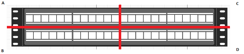
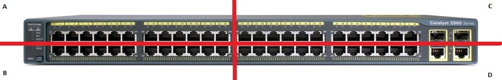
To start we are going to take our patch panel and switch and divide them into 4 quadrants. This works even if the patch panel is in thirds. The idea is simple, divide the ports horizontally so half the ports are on the top and half on the bottom. Do the same thing vertically for left and right. This effectively gives us 1/4 of the ports in each quadrant that will allows us to follow another desired arrangement of all the top cables going to the upper cable management, and all the bottom cables going to the bottom. Coinciding with that, half the cables go to the left of the rack, half to the right. In the end you will see how this makes bundling better.
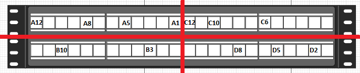
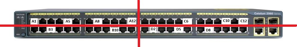
Below is an example of dividing a patch panel and a switch visually into quadrants.
Now that we have divided these two pieces into quadrants we need to think logically about numbering to make the cabling structure work. There are a few ways you could do the counting so long as the end result is the same. The key is that each quadrant must count in one direction on the patch panel, and the opposite on the switch. I choose to count the switches quadrant rising starting with the left most port in each. In this case I count downwards from the left most ports on the patch panel. Others may count up from the outer most ports and inner most ports for the switch and patch panel respectively. Again, the key is to reverse the action of each quadrant between the patch panel and switch. Numerically represented below these two options.
Option 1
Patch Panel:
A 1-2-3-4-5-6-7-8-9-10-11-12 | 1-2-3-4-5-6-7-8-9-10-11-12 B
———————————————————————————-
C 1-2-3-4-5-6-7-8-9-10-11-12 | 1-2-3-4-5-6-7-8-9-10-11-12 D
Switch:
A 12-11-10-9-8-7-6-5-4-3-2-1 | 12-11-10-9-8-7-6-5-4-3-2-1 B
———————————————————————————
C 12-11-10-9-8-7-6-5-4-3-2-1 | 12-11-10-9-8-7-6-5-4-3-2-1 D
Option 2
Patch Panel
A 1-2-3-4-5-6-7-8-9-10-11-12 | 12-11-10-9-8-7-6-5-4-3-2-1 B
———————————————————————————-
C 1-2-3-4-5-6-7-8-9-10-11-12 | 12-11-10-9-8-7-6-5-4-3-2-1 D
Switch:
A 12-11-10-9-8-7-6-5-4-3-2-1 | 1-2-3-4-5-6-7-8-9-10-11-12 C
———————————————————————————
C 12-11-10-9-8-7-6-5-4-3-2-1 | 1-2-3-4-5-6-7-8-9-10-11-12 D
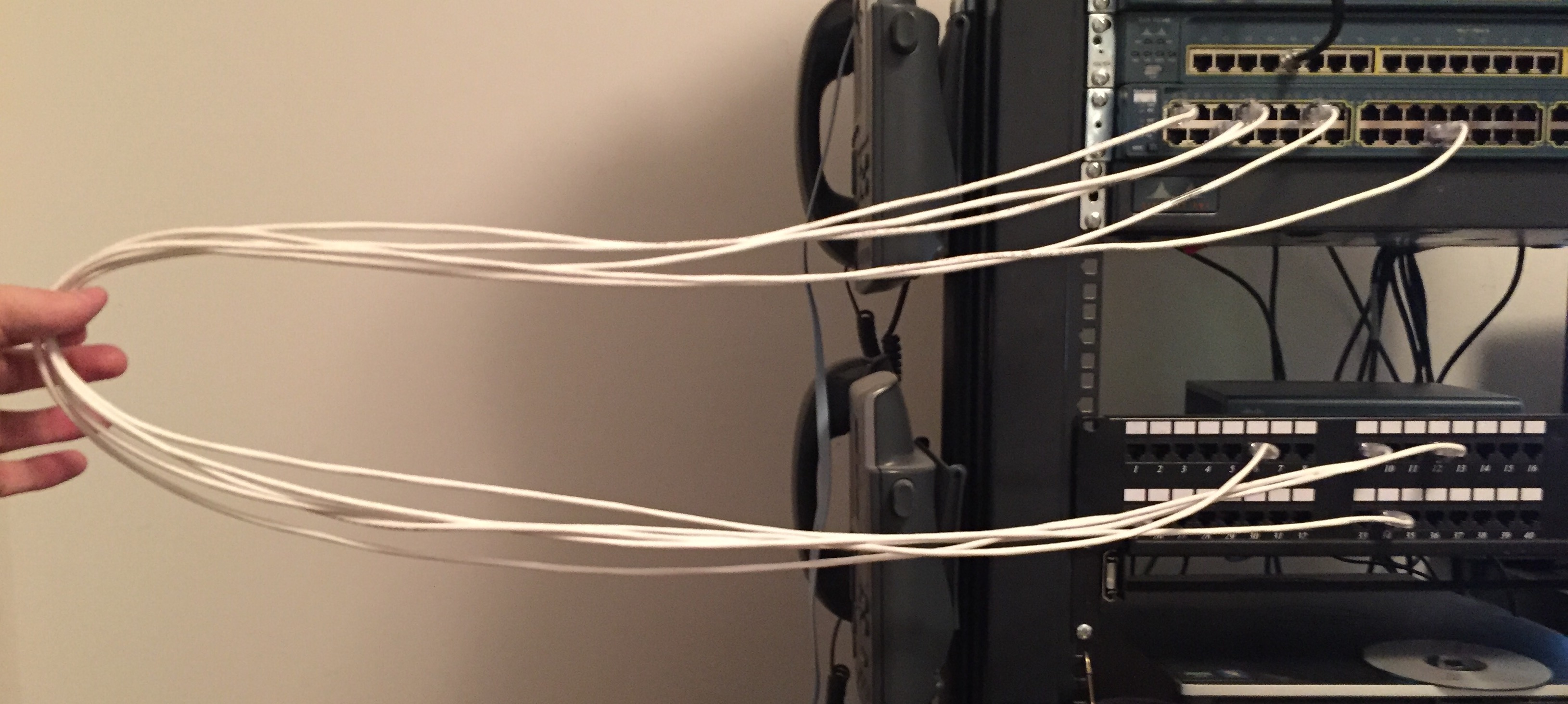
Now when it comes to cabling the trick is pretty simple to follow. Patch A1 to A1 between the switch and patch panel. As you do this you your service loop will stay within a small 12 port width from it’s closest patched and furthest patched quarter of the ports. What this means is that the so called service loop on the cables stays relatively lined up making a much more aesthetically pleasing binding when forced to use longer cables. For example I used the following switch and patch panel numbering just to represent how you would cable if not filling all of the ports.
As you can see I kept the quadrants in line. The left most port on the patch panel in quadrant A gets patched to the right most port on the switch in the same quadrant. Doing this means every port to the left you move on one device, you move in the opposite direction eventually converging on a cross pattern. This keeps that service loop relatively the same on each cable. See the demonstration picture below.
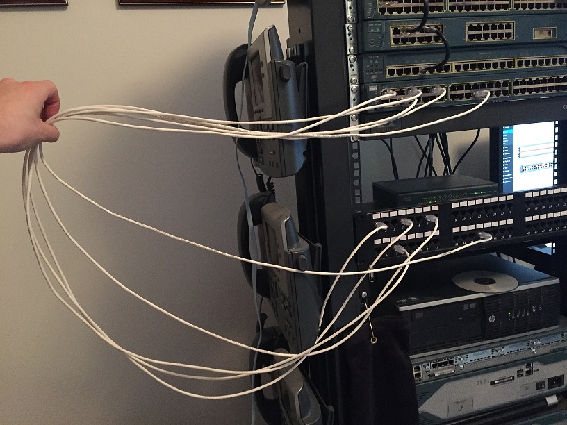
So contrast this picture i use the same cables, the same switch, and the same patch panel all in their same locations. I left the cables plugged into the switch where they were and modified the patch panel cabling to do a one to one match in port location with the switch. The number scheme looks like this.
Patch Panel
A 1-2-3-4-5-6-7-8-9-10-11-12 | 12-11-10-9-8-7-6-5-4-3-2-1 B
———————————————————————————-
C 1-2-3-4-5-6-7-8-9-10-11-12 | 12-11-10-9-8-7-6-5-4-3-2-1 D
Switch
A 1-2-3-4-5-6-7-8-9-10-11-12 | 12-11-10-9-8-7-6-5-4-3-2-1 B
———————————————————————————-
C 1-2-3-4-5-6-7-8-9-10-11-12 | 12-11-10-9-8-7-6-5-4-3-2-1 D
Doing this causes the cabling to be in a less aesthetically pleasing bundle due to the service loops being essentially a varying distance from the vertical center of the rack as seen in the demonstration image below. Again, I used the same exact cables and equipment as the above picture using our theory of cabling outlined at the beginning of this post.
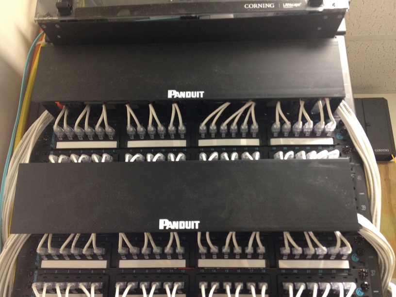
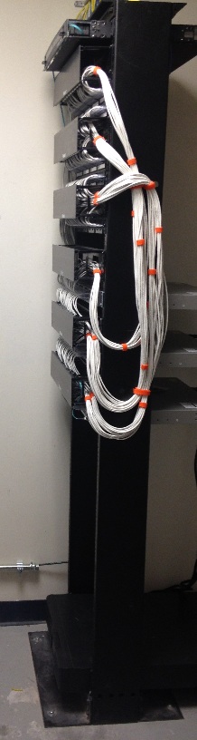
As you can see the practice outlined at the beginning of this post helps to keep the cabling bundles a little bit neater when it comes to being forced to use the wrong length cables because it’s what is on hand. With cable management the outcome can be much more pleasing to outlook sending the appropriate cables int he appropriate direction. As an example check out the photos below. Unfortunately due to circumstances vertical cable management couldn’t be installed however, notice how the cable bundles are grouped uniformly making it look much neater than over 48 cables of different service loop lengths. Notice with correct placement the patch panels can be easily read and pulled out due to the top cables going up and cascading out the sides. The same being with the bottom ports. I don’t have a picture however the same cable management is in place at the switches as well.